
3D Print Quote Checklist for Engineers
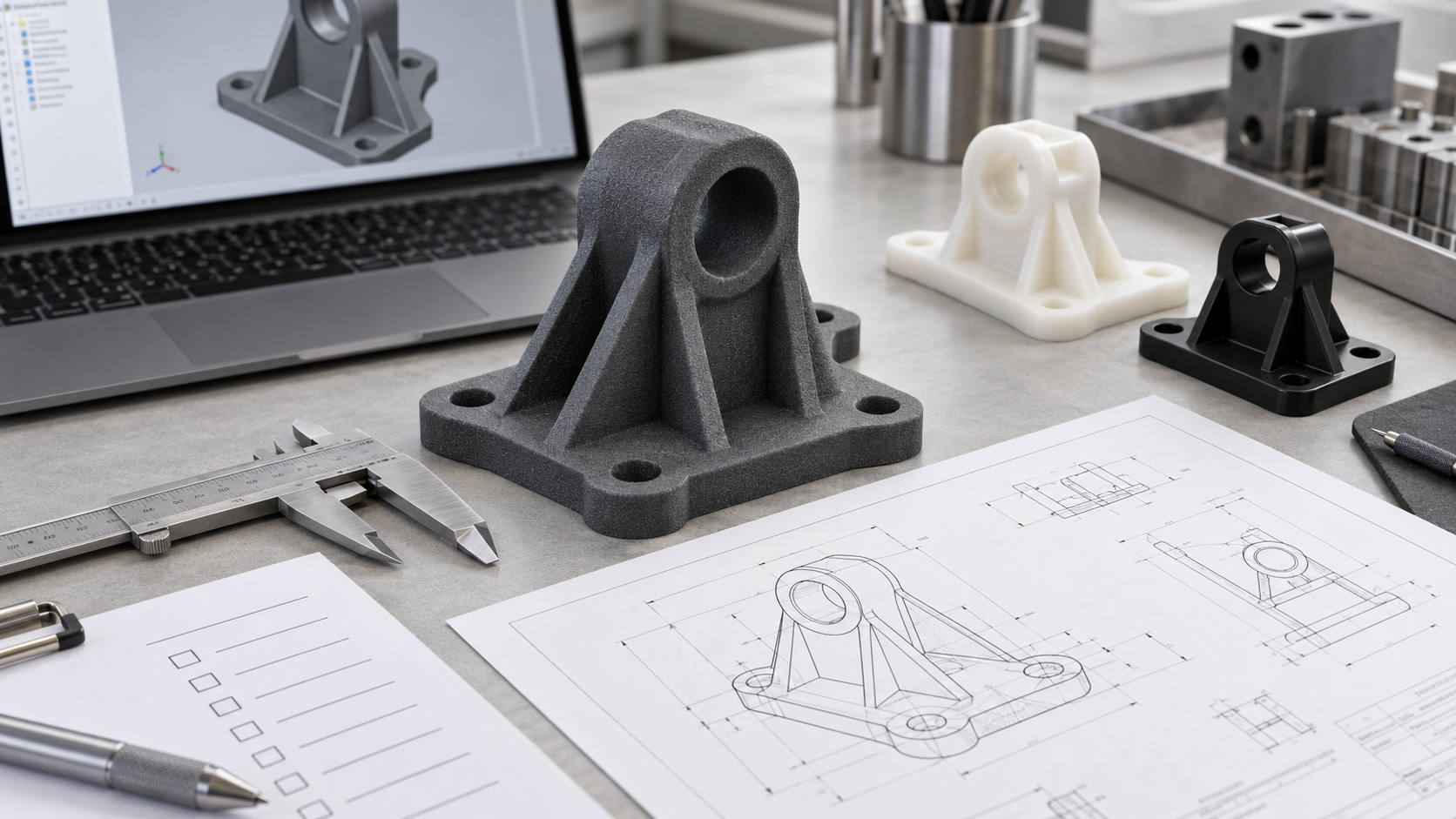
A successful additive manufacturing project starts before the CAD file reaches the production team. The geometry must be printable, but the quotation also depends on information that is often missing from the first submission: material, quantity, finish, tolerances and critical dimensions.
A complete input lets the manufacturer assess the part against the process, identify risks early and quote the intended result rather than a generic version of it. Use the checklist below before sending your files.
1. Check the CAD geometry and units
Start with a closed, valid solid model. Open surfaces, duplicated bodies, self-intersections and unintended gaps can prevent reliable processing or create an incorrect interpretation of the part.
Confirm the unit system in the CAD file and state it separately in the quotation request. A model created in millimetres but interpreted as inches can produce an unusable result, even when the geometry itself is correct.
Also check the overall envelope. Norra’s usable build chamber for MJF is 380 x 284 x 380 mm. The usable SLS build chamber on the EOS FORMIGA P 110 is 200 x 250 x 330 mm. Parts that exceed these dimensions may need to be split, redesigned or assessed for another production route.
If the part contains internal cavities, include a realistic powder removal strategy in the design. Fully enclosed voids cannot be produced in polymer powder bed fusion. Openings must be large enough for powder to escape during cleaning.
Compare STL and STEP file formats before exporting your CAD model.
2. Specify the material and process
Do not leave material selection open if the application has defined requirements. Norra’s standard MJF materials are Gray Nylon, PA12, and ESD Nylon, PA12. Standard SLS materials include White Nylon, PA2200, Reinforced Nylon, PA3200GF, and Flexible TPU 1301.
PA11 is available on request for food contact and elevated temperature applications. It is not a stock material, and lead time is quoted per job.
Material choice affects strength, flexibility, appearance, conductivity and the interpretation of thin features. State the intended use, loading, temperature exposure and any contact requirements so the material can be reviewed against the application.
Explore our material and technology options to find a suitable match for your application.
3. Mark critical dimensions and tolerances
A general dimensional tolerance is not a substitute for identifying functional features. Mark datums, mating surfaces, hole locations, bearing seats, snap fits and any dimensions that control assembly.
Norra’s published MJF dimensional tolerance is plus or minus 0.3 percent of the nominal dimension, with a lower limit of plus or minus 0.2 mm. For SLS, it is plus or minus 0.3 percent, with a lower limit of plus or minus 0.3 mm.
Design mating features with the process in mind. Recommended MJF clearance is 0.4 mm for fixed connections and 0.7 mm for moving parts. For SLS, the recommendations are 0.1 mm for fixed connections and 0.5 mm for moving parts.
MJF supports wall thicknesses down to 0.6 mm, or 0.7 mm for unsupported walls. Its minimum hole and pin diameter is 0.5 mm. SLS supports 0.5 mm supported walls and 0.6 mm unsupported walls, with a minimum hole diameter of 1.5 mm and minimum pin diameter of 0.8 mm.
These values are design limits, not a guarantee that every thin feature will perform as a functional component. Identify the features that matter so they can receive specific attention.
Review our design guidelines for more information on wall thicknesses, clearances and feature sizes.
4. Define surface finish and marking requirements
State whether the part should have the standard fine matte finish straight out of the machine, or whether it needs further treatment. Norra offers cleaning and shot peening, vapor smoothing and dyeing in-house. Vapor smoothing on the AMT SF50 seals the surface and produces a finish comparable to injection moulding.
For engraved and embossed details, allow at least 1 mm in both depth and height in MJF and SLS. Include the required colour, masking areas and surfaces that must remain untreated.
5. Confirm quantity, delivery and inspection needs
Provide the required quantity, target delivery date and whether parts are prototypes, production components or replacement parts. Include inspection requirements, a measurement report request and any acceptance criteria that are important to the application.
For standard Gray Nylon PA12 in MJF, published lead times are 3 working days for Express, 5 working days for Standard and 20 working days for Planned production. Reviewed jobs depend on material, process, current workload and post-processing.
Add a drawing or marked-up PDF when the CAD model alone does not communicate functional intent. A clear package should contain the geometry, units, material, quantity, finish, tolerances and critical dimensions. If additive manufacturing is not the right option because of extreme precision, material requirements or annual volume, that should be identified during review rather than after production begins.
Compare our lead time options when planning your order.