
When Does 3D Printing Become Production Manufacturing? Lessons from Scaled Polymer Production
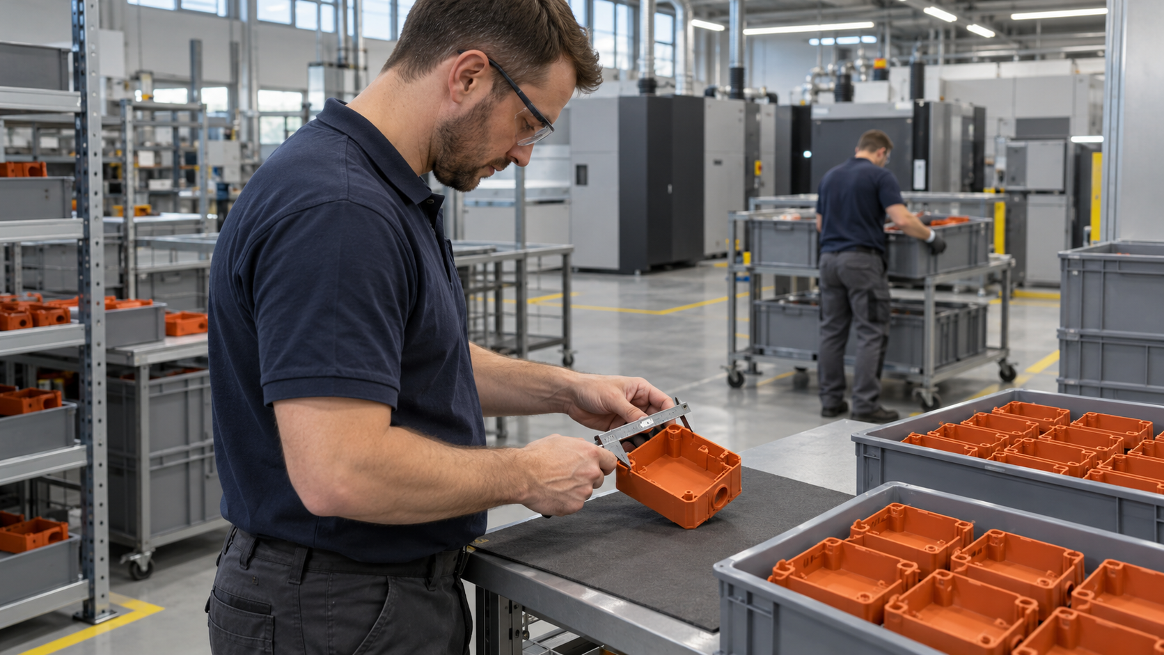
Part consolidation can reduce the number of components in a product, but printing one part instead of assembling several is not automatically an improvement. The consolidated design must still meet requirements for strength, movement, inspection, maintenance and production cost.
For polymer powder bed fusion, the strongest candidates are often brackets, housings, ducts, covers and assemblies that contain many individually manufactured pieces. MJF and SLS can produce complex geometries without mould costs, making it possible to test a consolidated design before committing to tooling. The decision should be based on the complete function of the assembly, not only on the number of parts removed.
Start with the assembly function
Review the existing assembly and identify what each component does. Separate structural functions from fastening, alignment, sealing, protection and service access. This helps distinguish useful consolidation from simply combining parts that are easier to manufacture separately.
A bracket may combine mounting features, cable guidance and protective covers. A housing may integrate ribs, bosses and locating features. In each case, ask whether the printed geometry can provide the required interfaces without introducing new risks.
The main questions are:
* Which fasteners, clips or alignment features can be eliminated?
* Which surfaces must remain accessible for installation or inspection?
* Does the consolidated part need to move, flex, seal or carry a load?
* Can the part be cleaned, finished and inspected after printing?
* Will a failure require replacing the whole component rather than one small part?
Consolidation is less suitable when the assembly needs frequent repair, uses materials with different functional requirements, or depends on components that must be replaced independently. It is also a poor fit when production volume makes injection moulding more economical. Polymer powder bed fusion has no tooling or mould costs, but unit cost does not fall with volume in the same way as injection moulding.
Design clearances around the function
Clearance must be designed around the intended connection. A fixed connection and a moving interface need different allowances, and the process and material influence the result.
For MJF, Norra recommends 0.4 mm clearance for fixed connections and 0.7 mm for moving parts. For SLS, the corresponding recommendations are 0.1 mm for fixed connections and 0.5 mm for moving parts. These values are starting points for design. The final fit also depends on geometry, nominal dimensions, orientation, finishing and the tolerance required by the application.
Norra quotes MJF dimensional tolerance at plus or minus 0.3 percent of the nominal dimension, with a lower limit of plus or minus 0.2 mm. For SLS, the lower limit is plus or minus 0.3 mm. Functional interfaces should therefore be identified early, with critical dimensions checked against the process tolerance rather than treated as nominal CAD geometry.
For moving assemblies, avoid long, tightly enclosed sliding surfaces unless the cleaning and finishing process has been considered. Provide access for powder removal and allow enough clearance for the intended movement after post-processing.
Provide a route for powder removal
Powder bed fusion does not remove powder from a fully enclosed void. Any internal cavity in a consolidated part needs openings large enough for powder removal. This is a basic design condition, not a post-processing detail.
The opening should be placed where it can be reached during cleaning and where remaining powder will not collect in a low point or narrow passage. If the cavity must remain sealed in operation, consider how it will be closed after cleaning. A separate plug, a bonded cover or another serviceable solution may be more appropriate than a permanently enclosed printed void.
This requirement can determine whether an assembly should be consolidated at all. A housing with internal channels may be a good candidate if the channels can be cleaned and the access openings do not compromise the product. If they cannot, separate parts may be easier to validate and maintain.
Check interfaces and finishing together
Consolidation changes the way loads and forces move through the part. Reinforce mounting points, avoid sharp transitions where practical and verify that walls and pins suit the selected process. MJF supports wall thickness down to 0.6 mm, or 0.7 mm when unsupported. SLS supports 0.5 mm supported walls and 0.6 mm unsupported walls. These are process limits, not automatic recommendations for load-bearing features.
The as-produced surface is a fine matte finish. Norra also provides cleaning and shot peening, vapor smoothing and dyeing. Vapor smoothing seals the surface and produces a finish comparable to injection moulding. These treatments can affect interfaces, so fit checks should use the planned post-processing route.
When consolidation is the right choice
A consolidated MJF or SLS component is worth evaluating when it removes assembly work, reduces alignment risks, simplifies a complex shape or makes a low-volume design easier to produce. It is not the right choice when serviceability, material separation, inspection access or high-volume economics dominate.
The practical workflow is to map the assembly functions, mark all fixed and moving interfaces, design powder-removal openings, check process tolerances and review the finished part as it will be cleaned and used. That evaluation gives engineers a clearer basis for deciding whether one printed component should replace an assembly.